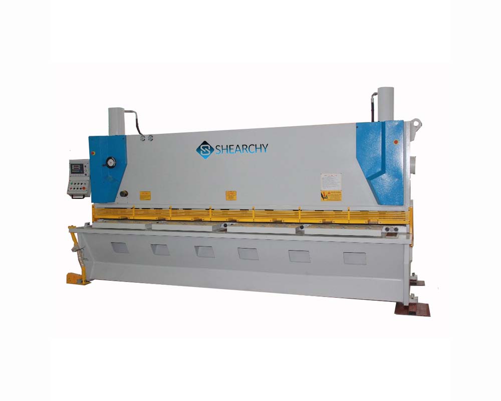
Hydraulic Guillotine Shear gears manufacturing materials and heat treatment have a great influence on its carrying capacity, size and weight.
Hydraulic Shearing Machine Gears Manufacturing
Before the 1950s, the gears of hydraulic plate shears were mostly made of carbon steel. In the 1960s, shearing machine manufacturers turned to use alloy steel. In the 1970s, the manufacturers mostly used case hardened steel.
Gears Classification
According to the surface hardness, we can divide gears into two kinds: soft tooth surface and hard tooth surface.
Soft and Hard Tooth Surface Hydraulic Guillotine Shear Gear
Soft Tooth Surface Gear
The load-carrying capacity of the gear with soft tooth surface is low. But, it is easy to manufacture and has good running in performance. They are mostly used in machinery with unlimited transmission size and weight, as well as general machines with small production volume.
Because the small wheel has a heavy load in the matching gear of the hydraulic guillotine shear machine. In order to make the arge and small gears’ working life approximately equal, the hardness of small gear tooth surface is generally higher than that of large gear.
Hard Tooth Surface Gear
The load-carrying capacity of gear with hard tooth surface is high. After fine cutting, and then surface or carburizing quenching to improve the hardness. But in the heat treatment, the gear of plate shear machine will inevitably deform. Therefore, after heat treatment, the manufacturers must carry out grinding or fine cutting. In order to eliminate the error caused by the deformation and improve the shearing machine accuracy.
How to Install CNC Guillotine Shears?
Hydraulic Shear Machine Gears Installation Requirements
- The axis of the pinion shaft is parallel to the axis of machine . The levelness is 0.04mm/m. And the elevation difference is not more than ± 1mm.
- When there is no requirement in the drawing, we can choose the backlash of large and small gears according to the actual situation.
- Engagement of large and small gears. Check the contact points:
Not less than 40% along the tooth height; not less than 70% along the tooth length; and in the middle of the tooth width.
- The coaxiality of pinion shaft and reducer shaft is 0.2mm.
- Coaxiality of the input shaft of the reducer, the motor shaft and the output shaft of the auxiliary reducer is 0.2mm.
- The coaxiality of auxiliary reducer shaft and auxiliary motor shaft is 0.2mm.

