Bending length of sheet metal has a great influence on the accuracy of work piece. The longer the sheet metal processed, the greater the brake press machines working load required. As a result, the inclination of the equipment and the deformation of the slider block become larger, which makes it more difficult to ensure the accuracy.
Press Brake Machine Slider Block Load
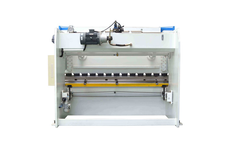
Brake Press Machines Block Structure
The slide block is welded by different shapes of steel plates. In the process of modeling, the details that have little effect on the results are negligible. In the analysis, we only keep the main structure of the slider. Because this structure has arbitrary 3D orientation and can adapt to the curve boundary model well. We can analyze the elastic deformation of the slider more accurately.
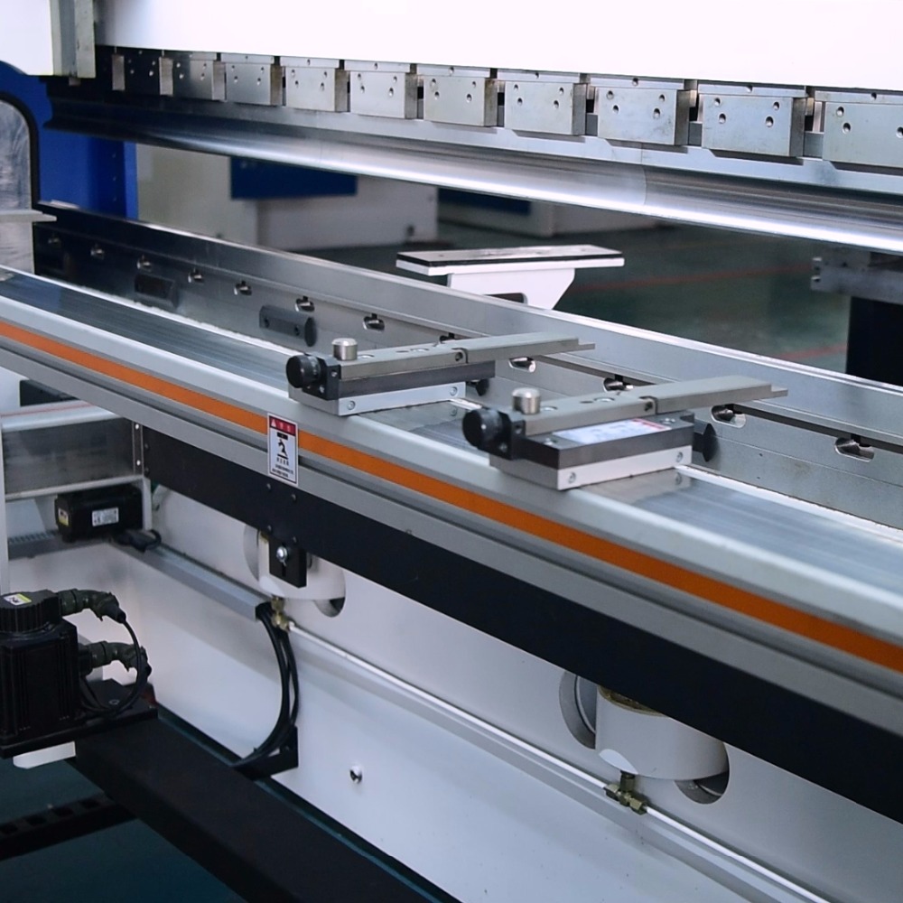
Hydraulic Press Brakes Slider Block Load Test and Analysis
Firstly, we need to fully consider the load and constraint of the hydraulic bending machine slider. In the actual working condition, the slider of the bending machine is always in the state of motion. Because of the static analysis of block slider, the constraint of the slider must be simplified and approximated. In other words, we impose a symmetric constraint on the nodes on the symmetry plane in the middle of the slider. The fixing of the sliding block is realized by the connection between the guide rail arranged on the rack and the rear part of the sliding block. So we put all the constraints on this part.
In addition, we apply the load on the contact part between the bottom of the hydraulic cylinder and the slider. Due to the relatively small vertical deformation of the slider, it belongs to small elastic deformation. Therefore, the bending machine applies uniform load to the stress surface at the bottom of the slide. The bottom of the slider and the brake press die linked by the connecting block ensures the force evenly transmitted from the slider to the upper die.
In the end, through in-depth analysis and setting the path, we extract the deformation deflection curve of the stress surface at the bottom of the slider. We found that the maximum displacement appears in the center of the slider and decreases gradually in parabola form towards both sides. At the same time, we can get the deformation displacement at any position in the direction of bending length, which provides data support for the design of deflection curve formed by wedges with different array angles.
Need Plate Bending Machinery?
Shearchy hydraulic CNC brake press machines have:
- CNC crowning system for improving quality
- Servo driven back gauge system for increasing speeds
- 3D capable graphical control unit to simulate bending sequences and collision points.
Welcome to contact us for more details!